While building our rotting-in-a-field rescue BMW 540it wagon for drift, we eventually came to the conclusion that a hydraulic handbrake would make a nice addition to the car. The wagon’s 4.4L V8 makes plenty of power, but still there are times when a quick lock of the rear wheels would be preferable to a clutch kick. When it came time to actually source parts and install the hand brake, however, we found that information was sparse for the E39 chassis. Nothing was available off-the-shelf like it is for more popular drift cars, so we had to do some research. These are our findings, and we hope they’ll help out future BMW drift builders. The methodology we used is likely to work for many 90’s and 2000’s BMWs. Fair warning: brake systems are pretty complex, so there is a lot of information in this article. Take the time to learn it now, and your installation will go smoothly. The standard disclaimer applies: work on and modify your car at your own risk. This article is for informational purposes only. Modifications to braking systems are particularly hazardous because brake failures are inherently dangerous. Thoroughly test any work you perform! Lastly, hydraulic handbrakes are for off-road use only.
Dual Caliper or In-Line?
There are two main flavors of hydraulic hand brake. Both use a master cylinder attached to a lever, but the dual caliper setup runs an entirely separate hydraulic system. In a dual-caliper setup, you mount another set of rear brake calipers (hence the name) and these calipers have a completely independent hydraulic system that routes to the hydraulic handbrake master cylinder, which has its own reservoir for hydraulic fluid. This is the preferred setup and will always have better performance than an In-Line setup. However, they are inherently more expensive because you need a whole new set of calipers, as well as a dual-caliper mount. On cars with steel suspension and hub parts, you can often just weld a couple of mounting points on in lieu of a bracket. For cars with cast aluminum components like our E39, this is realistically not possible. Additionally, for the E39, no dual-caliper mount bracket exists at this time.
Let’s Get In Line
This leads us to the desire to install an in-line setup. Not only will it save some money on our budget drift sled, but it avoids having to design and fabricate a dual-caliper bracket. I searched for a quality how-to on installing an in-line setup and quickly learned two things:
1. I had no idea how brake lines and fittings worked.
2. Neither did anyone else.
For the most part, the “how to” videos I found involved teenagers cutting up their factory brake line systems and installing random fittings and then slapping on some teflon tape in hopes of reducing the leakage. More than once I even saw recommendations for completely deleting the capability of the foot brake to activate the rear brakes, which is a pretty unsavory option.
Design Goals
I decided that I wanted my setup to achieve the following:
Modify the factory brake system as little as possible.
Be as tidy as possible.
Not disable ABS
Above all, not leak.
That third item is pretty tricky, it turns out, as most people will insert their handbrake MC lines with fittings between the ABS module and the rear calipers. Often, they’ll hydraulically bypass the ABS module in the process. Furthermore, pulses from the ABS pump via the ABS module might not be effective when routed through the hydraulic handbrake MC. The wagon’s ABS doesn’t currently work (due to a sensor being broken), but we would like the ability to switch ABS on and off in the future. To achieve this goal, the in-line setup had to hydraulically preserve the ABS system.
Brake Line Lingo
We’ve already discussed a few terms, but here are the essentials:
Master Cylinder: Has an inlet and an outlet. When an outside force acts on the master cylinder, such as a foot pedal or handbrake lever, it pumps fluid from the inlet to the outlet. When the outside force is released, fluid flows back the other way. For most braking MC’s, the inlet is a reservoir. For factory foot brake master cylinders, they have a separate outlet for front and rear brakes. On BMW’s they’ll be labeled “H” for rear and “V” for front.
Tubing: Small metal pipes for carrying your brake fluid. Usually steel, but available in copper-nickel alloys. They come in various sizes, but on BMWs they are all either 6mm outer diameter (“OD”) or 4.75mm OD. The 4.75mm OD is, for all intents and purposes, interchangeable with 3/16” OD tubing.
Hoses: The other vessel for carrying brake fluid. Often they use -#AN style fittings. On factory systems these are used between the body and the calipers to allow for movement of the wheels, but also in other parts to account for vibration or chassis flex.
ABS: Anti-lock Braking System.
DSC: Dynamic Stability Control. BMW started integrating this system, and its predecessor ASC, in the late 90’s. It significantly complicates hydraulic routing and you’ll need to disable it to do any drifting. Fortunately, a button press (or long hold) is often enough to disable it. Otherwise you can pull fuses or a wheel speed sensor, or a yaw sensor. DSC works via the ABS Block and DSC pre-charge pump.
ABS Module or “block”: An electro-hydraulic block with solenoids that send pressure pulses to pulse the brake calipers and prevent lock-up. Fittings will be labeled “H” for rear and “V” for front fittings, along with L and R for right and left where applicable. An ABS pre-charge pump is used to recover pressure lost during activation.
Flare: The shape at the end of brake tubing that allows it to seal into fittings. BMW’s use the “bubble” flare, also known as ISO or DIN. Domestic and Asian vehicles us the “inverted” flare shape also known as the SAE/ Double flare. There are flare dimensions associated with each tubing size, so on a flaring tool you’ll see tool “anvils” for 4.75mm, 6mm, etc.
Flare nut: This is the nut that is installed onto the brake tubing before flaring. The male threads on the flare nut tighten into the female side of the joint, such as a union. M10x1.0 and M12 x1.0 are the two common BMW sizes.
Union: A female/female fitting used to mate two pieces of tubing, or tubing to another fitting. The unions have a seat for the tubing flare on the inside, so they MUST match the type of tubing flare you are using, which for BMW is bubble flare. Additionally, the union must match the thread spec of the flare nuts.
Banjo Bolt: A type of fluid fitting that allows you to point one end of the fitting in the direction of your choosing before locking it down.
AN fitting: A standard of fittings commonly used for flexible hoses. A number is associated with the size. For this project, we use -3AN sized fittings on a small flexible brake hose.
Tools of the Trade
Tubing cutter: A blade that rotates around the tubing to create clean cuts. Smaller ones will help you work in tight spaces.
De-burring tool: Sometimes one is included with the tubing cutter. You’ll need it to clean up your tubing cuts.
Flaring tool: There are tools for Bubble Flare and tools for Inverted Flare. I ended up needing both. They consist of a clamp that has holes for each size tubing, and a part that holds the “anvil” that presses into the tubing to force it into the flare shape. The Bubble flare tool requires only one press, where the Inverted requires two pressing steps, hence the “double” flare name for the inverted.
Tubing bender: Helps you make smooth bends in your brake tubing.
Tubing straightener: Straightens out kinks in the tubing and will help improve the look of your tubing routing dramatically. I didn’t use one of these, but wish I had.
Gloves and shop rags: You’ll want a lot. You’re going to make a mess.
Fluid extractor: In a pinch, use a turkey baster.
Brake bleeder: I swear by the Motive pressure-style bleeder, with the “dry” method. In this instance, it doubles as a pressure tester of your hydraulic joints.
Brake fluid catch bottle: I recommend at least two for faster bleeding.
Flare wrenches: Better grip than standard wrenches when working with brake fittings.
CRC Screwloose: You’re going to want to treat the factory unions with this prior to trying to loosen them.
INPA/DIS or other BMW software: You’ll want to be able to activate the ABS/DSC Hydraulics Bleed feature. I use a launch x431 and the EZ Diag phone app, or BMW’s DIS program on a laptop. There are lots of programs like this out there.
Realoem.com: This website has parts diagrams. These diagrams prove extremely useful for planning out hydraulic system modifications.
Major Parts to Buy/Make
You’ll need a few ingredients. This is where having an uncommon drift car is difficult; most common cars you can just go DriftHQ or similar site and buy a kit.
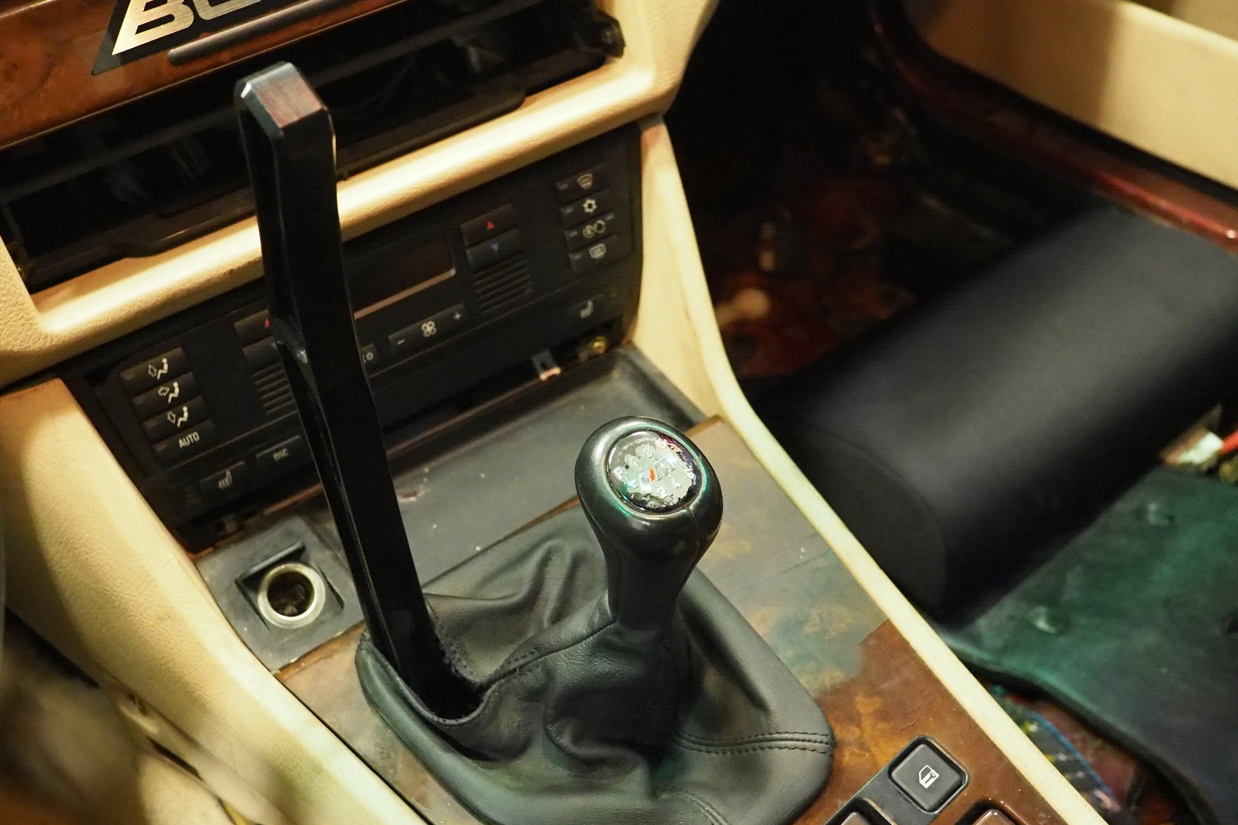
Handbrake: We went with the DriftHQ compact. This one was pretty easy to mount due to its compact size, but if you aren’t looking for a “stealth” install underneath the console, consider a bigger mount that is reinforced for stiffness.
Master cylinder: The wilwood master cylinder is pretty standard these days. It was included with our handbrake from DriftHQ.
Brake Fluid: You’re going to need a lot. Buy a few liters of cheap DOT4 and then after the installation is done and the leaks are all fixed, come back and flush out with something good like Motul, SRF, etc.
Mounting bracket: You’ll need to weld or otherwise fasten some sort of plate to the trans tunnel so you can secure the handbrake. The DriftHQ compact comes with a steel backing plate that you can weld on. We chose to take advantage of three nutserts around the shifter, and fabricate a plate that both mounted the handbrake and bolted down to the trans tunnel via the nutsert threads.
Tubing: We did this project with 15 feet of 3/16” copper-nickel tubing. I think it would work better if 6mm tubing was used, but 6mm tubing is rare and complicates the installation significantly due to unavailability of fittings. I highly recommend the more expensive copper-nickel tubing over steel. It is MUCH easier to bend by hand, and easier to flare as well. It’s available on Amazon through vendors such as The Stop Shop.
I give this install two plumbs up
For our in-line hydro setup to work, we need to plumb the outlet side of our handbrake master cylinder to the rear brakes. Instead of a reservoir (like would be used in a dual-caliper setup), the inlet side of the handbrake MC will be plumbed to the outlet of our factory foot brake master cylinder. Specifically, we will want to place our handbrake MC “in line” of the hydraulic circuit between the “H” rear outlet and the rear calipers.
This is where it gets tricky.
A common method is to run entirely new tubing from the “H” outlet of the factory master cylinder directly to the inlet of the handbrake master cylinder, and then run the outlet of the handbrake MC directly to the rear calipers. This setup hydraulically bypasses the ABS module. It’s fine if you have no interest in ever having working ABS, but additionally it requires you to cut a lot of factory tubing, and run a lot of your own tubing as well.
What I chose to do was insert the handbrake MC inline between the factory foot brake master cylinder and the ABS block. The ABS block is where the hydraulics are split from one line for the rear circuit into two, for rear left and rear right brakes. By placing our handbrake MC this way, we have to disturb only one factory line instead of two.
As luck would have it, there exists a union fitting in this factory line. It is piece 11, “intermediate piece” part number 34326757285 on this diagram:

On the E39 540i, it is located on the driver’s side engine bay, near the firewall, just above the heater control valve. Be sure the engine is completely cool before cracking this fitting open, because you wouldn’t want flammable brake fluid dripping onto hot exhaust.
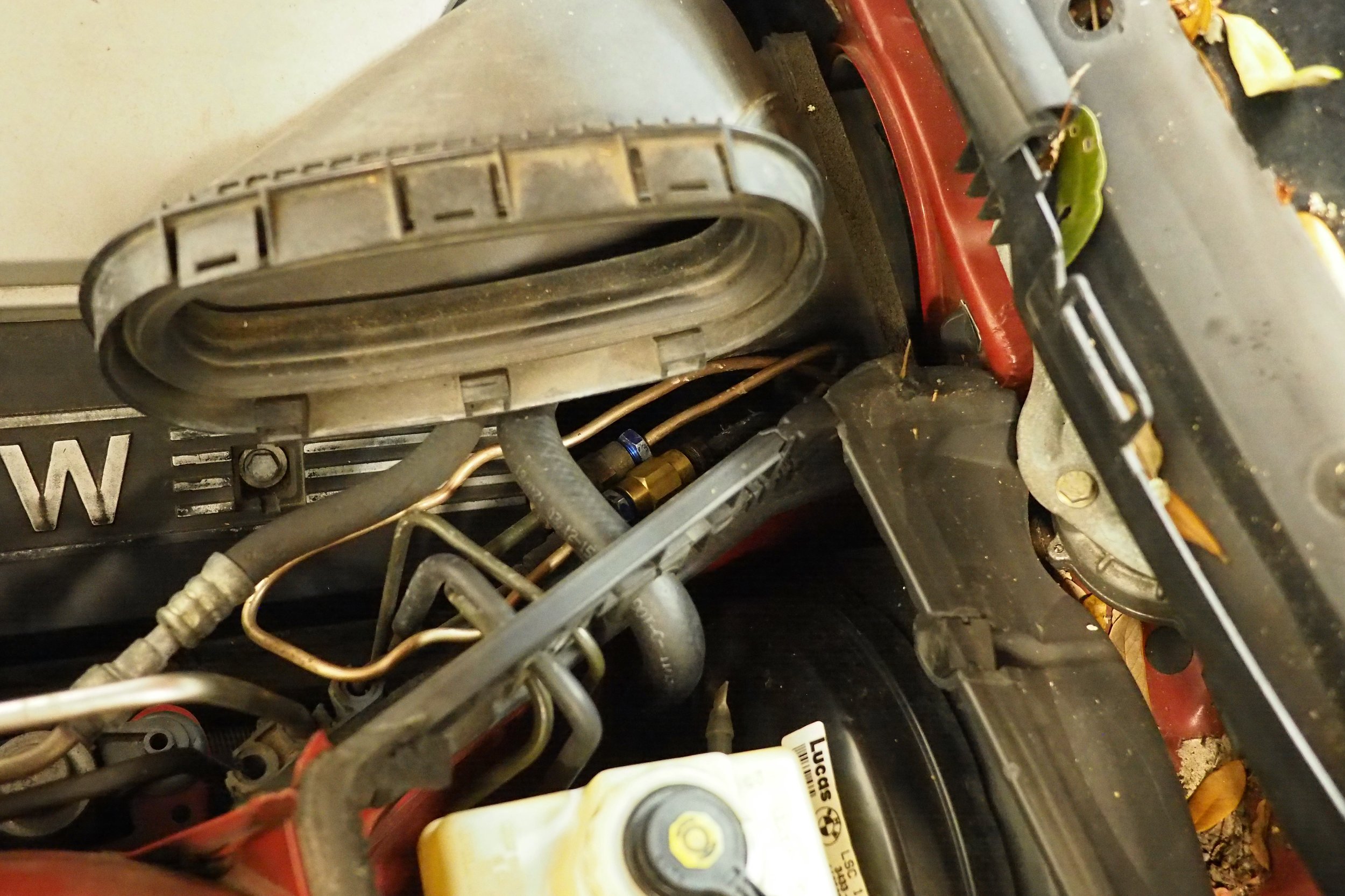
Brake line union fittings by the driver side cabin air filter housing. Please pardon the leaves and terrible tubing bends.
By opening this fitting, we’ll intercept fluid coming out of the rear “H” circuit leaving the foot brake MC, but before it reaches the ABS Module. This way, we won’t interfere with operation of the front brakes, and we’ll tidy up the routing some by placing our in-line hydro before it is split to left and right sides. In the simplest terms, we will open this union and connect the upstream side (from the foot brake MC) to the inlet of our handbrake MC, and then connect the downstream side (towards ABS block) to the outlet of our handbrake MC. Sounds easy, right? Two runs of tubing and you’re done.
A Whole Lot of Random Fittings
Not so fast. As with all things BMW, it turns out this is way more difficult than it needs to be. And, furthermore, most of the generic kits you’ll find for drift cars are geared towards Domestic or Asian cars that use the Inverted/Double flare standard, not the Bubble flare standard like BMW. There are several different ways you can hydraulically connect the Wilwood handbrake MC to the factory system, but here is how I managed to do it.
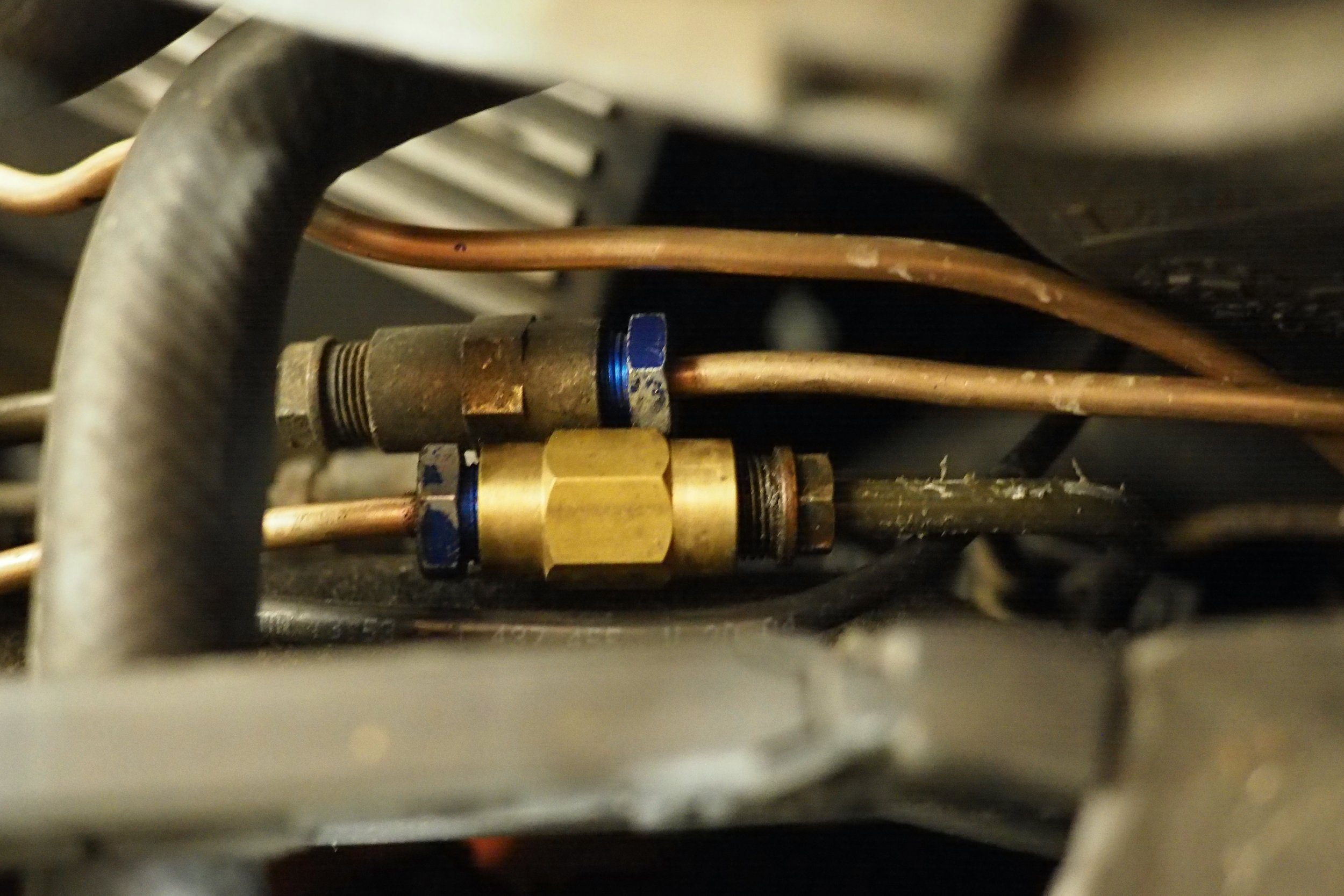
The Wilwood master cylinder uses a 7/16”-20tpi inlet fitting. A reservoir will thread into this on a dual-caliper system, but for in-line we need to find a way to connect our factory line to this. The factory union we are breaking open (see above diagram) is 6mm tubing with a 6mm bubble flare, and M12x1.0 bubble flare nuts. Unfortunately, there is pretty much no way to adapt 6mm tubing to 7/16”-20tpi, but if you step the tubing size down to 3/16” (or 4.75mm, remember they’re interchangeable), that size tubing can be adapted.
So here is BMW secret trick number one. Although in general, 4.75mm tubing uses M10x1.0 flare nuts and 6mm tubing uses M12x1.0 flare nuts, there is such thing as an M12x1.0 flare nut sized specifically for 4.75mm tubing. In fact, BMW even does this on some factory lines. Look at piece 34326755340, for example. It’s an almost 8 foot long section of tubing that has M12x1.0 flare nut on one end and M10x1.0 on the other. In fact, if you were great at bending but didn’t want to do any flaring, I think 34326755340 is probably long enough that you could just run two of them between the M12 union in the engine bay, through the trans tunnel, and into the cabin.
In a nutshell, you can use a union meant for 6mm M12x1.0 flare nuts as a reducer, with 6mm tubing coming in one side with a 6mm flare and an M12x1.0 flare nut (with 6mm interior diameter), and 4.75mm tubing coming out of the other side with an M12x1.0 flare nut (with 4.75mm interior diameter). One thing I’m not clear on is whether you should flare the 4.75mm tubing with the 4.75mm anvil, or the 6mm anvil. I tried 6mm, and it appears to work leak-free. It makes sense to me that the 6mm flare would be the one to use, because the union has a seat meant for a 6mm flare, but I was not able to find any documentation on this. Try at your own risk and test thoroughly; you don’t want these unions leaking onto your exhaust!
To recap: Install an M12x1.0 flare nut sized for 3/16” (4.75mm) tubing onto 3/16” tubing. Flare the 3/16” tubing with a bubble flare tool and the 6mm flare anvil. Thread the new M12x1.0 flare nut and your new tubing into the factory M12x1.0 union. Route the tubing into the cabin (I went through the trans tunnel, which is direct but also very hot. I haven’t tested this on track yet but I would advise some heat shielding at the very least). On the other end, you have a few choices to go from 3/16” tubing to the 7/16”-20 inlet. The easiest and most direct way is with this fitting from SRS Concept: SRS Concept 3/16" Tubing to 7/16"-20 Fitting
I haven’t personally tried this fitting, but it is definitely the simplest way, assuming that it works. The only downsides of using this fitting is that you’ll have to do a lot of tube bending to get this to work well, and you won’t be able to isolate the master cylinder from vibration which can cause fatigue in the fittings over time. A hose provides vibration isolation and eases routing. Furthermore, this fitting requires the Inverted/Double flare, and won’t work with the Bubble Flare tool we previously used. The tool is cheap so I recommend just getting the tool and trying out this SRS fitting.
For my installation, I used a 7/16”-20tpi banjo bolt with a -3AN male output. I then used a short DOT-approved brake hose with -3AN female ends. To adapt the 3/16” tubing to the -3AN female, I installed an M10x1.0 bubble flare nut on the tubing and performed a 4.75mm bubble flare. Initially, I used a fitting from Earl’s that is female M10x1.0 bubble on one side and male 3AN on the other. Both of these leaked. Do not use this fitting. I later got a fitting that was male 3AN fitting on one side and male M10x1.0 bubble on the other, and used a M10x1.0 bubble union to mate the 3/16” tubing with the M10x1.0 flare nut to the adapter fitting and hose.
Inlet side recap:
Factory 6mm tubing-> factory M12 bubble flare nut -> factory M12 union->new 3/16” tubing with M12 flare nut -> m10 flare nut -> M10 union -> M10 to 3AN adapter -> 3AN hose -> 3AN to 7/16-20 banjo bolt -> wilwood master cylinder inlet.

Using the SRS fitting, your arrangement would be:
Factory 6mm tubing-> factory M12 bubble flare nut -> factory M12 union -> new 3/16” tubing with M12 flare nut -> SRS Concepts inverted flare adapter -> wilwood master cylinder inlet.
The outlet fitting is 3/8-24, and the Wilwood master cylinder even comes with an adapter for installing 3/16” tubing with inverted flare, using a common 3/8”-24 inverted flare nut. Please note that you need to use this adapter instead of just installing the flare nut directly into the master cylinder, because you need a seat for the inverted flare. Again, you could do a banjo bolt, 3AN hose, M10 arrangement but it is cheaper/simpler to just go straight to a 3/16” inverted flare with 3/8”-24 flare nut. On the other end of this run of new 3/16” tubing, you’ll install a M12x1.0 flare nut and use a new M12 union to install your new tubing to the factory tubing (piece 12 on the diagram) that leads to the ABS block.

Here are some links to the fittings I mentioned:
M12x1.0 Flare Nuts for 3/16" Tubing
3/1 6" Copper Nickel Tubing Kit: 15' of tubing with 3/8"-24 inverted flare nuts and one IF union
M12x1.0 6mm Bubble Flare Union
M10x1.0 4.75mm Bubble Flare Union
M10x1.0 3/16" Bubble Flare Nuts and Unions
7/16"-20 to 3AN banjo bolt kit
3AN male to M10x1.0 Bubble Male Adapter Fitting
SRS Concept 3/16" Tubing to 7/16"-20 Fitting
4.75mm tubing, pre-flared, with M10 and M12 fittings, 2351mm length
Wilwood Handbrake Master Cylinder
DriftHQ Compact Handbrake/ Wilwood MC Combo (Pull-Back, inline)
Leak Checks and Bleeding
During the installation process, you’ll have leaked an immense amount of brake fluid out everywhere, unless you chose to empty the brake fluid reservoir with an extractor ahead of time. Either way, you’ll have air in your system that now you’ll need to bleed out. It is customary to “bench bleed” the handbrake MC prior to plumbing it up in the car. I would advise bleeding all four calipers but for the sake of brevity, I’ll only discuss the rear system.
After jacking up the car and removing the rear wheels (use quality jack stands, please!), attach bleeder catch bottles to the caliper bleed nipples. Go ahead and open both of the bleed nipples (11mm wrench on the E39). Fill the brake reservoir with fluid. Attach the Motive power bleeder and pump it up to roughly 10psi. If you exceed 10psi, you’ll warp and discolor the reservoir some, so don’t do that. While the motive is pushing brake fluid into your catch bottles, inspect all of your joints for leaks. After bleeding the reservoir down to just above the minimum mark, close both of your bleeder screws, remove the motive, and refill the reservoir. Re-attach the motive and pressurize it to 10psi again. Open the caliper bleed screws and give your hydraulic hand brake a firm pull. Since the caliper bleed screws are open, the handbrake will travel all the way to the back before stopping. Check for leaks at your fittings and slowly release the hand brake. The pressure from the Motive will force fluid (and trapped air) into the Wilwood MC as you release the handbrake. Do this a couple of times to move air downstream into the catch bottles. It helps if you pull on the brake somewhat aggressively to really push any air or contaminants through the system. Tapping on the calipers with a mallet also helps free up air bubbles. Stop and refill the reservoir as necessary. Once you’ve pulled the handbrake a few times and it feels like the air is out, repeat this process except with the foot brake. This step is where you are most likely to see leaks.
On an in-line hydro, depressing the footbrake pressurizes the inlet side of the handbrake’s master cylinder. This will make the handbrake lever jump forcefully to the forward position. It is prudent to have some sort of stop, either something that the handle hits against, or something built into the handbrake mount, to brace the master cylinder hydraulics against this pressure. Depressing the foot brake will send fluid through the handbrake master cylinder and then downstream (in our case, through the ABS block) to the rear calipers.
Because we opened the hydraulic system upstream of the ABS block, air will be trapped in the ABS block. Use a software such as DIS to activate the ABS / DSC bleeding function. This will help move any trapped air out of the ABS block.
Once you’ve thoroughly bled the system (I used almost 4 liters by the time I was done fixing leaks), you should be good to go.
Thoughts on In-Line Hydro Brake Performance
During initial testing, I noticed the biggest disadvantage of the in-line hydro system is that multiple pulls of the hydro brake without use of the foot brake seemed to reduce effectiveness of the hydro brake. Stepping on the foot brake a bit seemed to help restore it to normal. Additionally, multiple pulls on the handbrake meant that the next step of the foot brake was a bit longer before the brakes enabled. Bleeding helped but did not fix this problem. My hypothesis is that repeated pulls moves fluid downstream towards the calipers, but doesn’t replenish the inlet side enough without a tap from the foot brake as well.
Regarding brake strength, a hydraulic handbrake setup like this isn’t power-assisted with a brake booster like the foot brake. Inherently it isn’t as strong. Even with a strong pull, it wasn’t exactly locking up the rear brakes easily. I intend to upgrade to a high-bite rear pad to help improve locking. I haven’t fixed my ABS yet so I’m unsure on if it will still work or not. Honestly I’m not hopeful but one day we’ll find out, and I’ll update this article.